Skip to content
πŸ”— DIY TOWING & FLAT TOWING

Trailer Wiring Diagram: Complete Guide to 4-Pin, 5-Pin, 6-Pin, and 7-Pin Connectors

Published Β· Updated Β· 12 min read
MarkUpdated Apr 15, 2026SAE J2863 Standard

Key Takeaways

  • βœ“**4-pin** handles basic lights; **7-pin** adds brakes, 12V power, and reverse lights
  • βœ“Standard colors: white=ground, brown=tails, yellow=left, green=right, blue=brakes
  • βœ“Corroded ground connections cause **over 70%** of trailer wiring failures
  • βœ“Electric trailer brakes **require** a 7-pin connector β€” 4-pin cannot carry brake signals
  • βœ“Always test with a 12V test light **before** your first tow β€” not at the boat ramp

Key Takeaways

  • 4-pin handles basic lighting; 7-pin adds brakes, 12V power, and reverse lights
  • Standard wire colors: white=ground, brown=tails, yellow=left, green=right, blue=brakes
  • Corroded ground connections cause over 70% of trailer wiring failures
  • Electric trailer brakes require a 7-pin connector and brake controller
  • Always test every function with a 12V test light before your first tow

Trailer wiring looks intimidating until you understand the pattern. Every connector β€” whether it has 4 pins or 7 β€” follows the same color-coded logic established by SAE standards. Once you know what each color does, you can wire, troubleshoot, or upgrade any trailer connector in your driveway. This guide covers every standard connector type with pinout diagrams, wire colors, and step-by-step troubleshooting for the most common failures.

If you're setting up a tow vehicle from scratch, start with the right hitch type and then match your wiring connector to your trailer's needs.


πŸ’°
DIY TOWING & FLAT TOWING

What Are the Standard Trailer Wiring Colors and What Do They Mean?

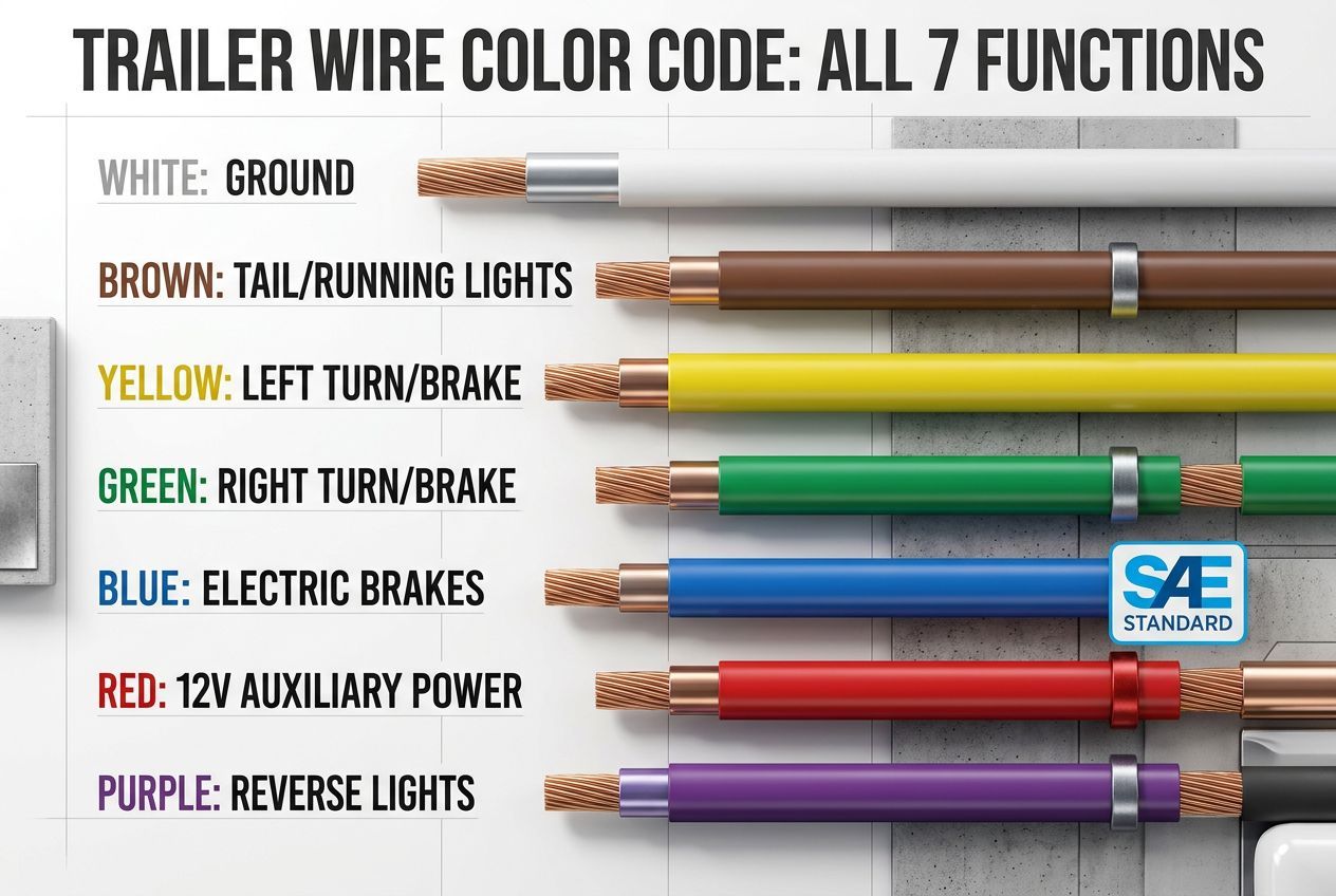
Trailer wiring uses a universal color code established by SAE (Society of Automotive Engineers) standard J2863. Every trailer manufacturer in the U.S. follows these colors, so a connector wired on a Carry-On trailer will match a connector wired on a PJ or Big Tex.

What Are the Standard Trailer Wiring Colors and What Do They Mean? β€” data table
Wire Color Function Circuit Pin (7-Pin RV)
White Ground Return path for all circuits Center pin
Brown Tail / Running Lights Always on when headlights are on Pin 1
Yellow Left Turn / Brake Combined turn signal and brake light (left side) Pin 2
Green Right Turn / Brake Combined turn signal and brake light (right side) Pin 3
Blue Electric Brakes Sends brake controller signal to trailer brakes Pin 4
Red or Black 12V Auxiliary Power Charges trailer battery, powers breakaway switch Pin 5
Purple or Orange Reverse Lights Activates when tow vehicle is in reverse Pin 6

Source: SAE J2863 standard, Hopkins Towing Solutions

The first four colors (white, brown, yellow, green) are universal across every connector type. The remaining three (blue, red/black, purple/orange) only appear on 5-pin, 6-pin, and 7-pin connectors. If your trailer only has basic lighting with no brakes or battery, a 4-pin connector using those first four wires is all you need.

Pro Tip: Wire colors on the tow vehicle side sometimes differ from the trailer side, especially on European vehicles. German and Japanese vehicles may use different color codes. Always use a 12V test light on the vehicle's harness to confirm which wire carries which signal before connecting β€” don't rely on color alone.


Trailer wiring color code diagram showing all seven standard wire colors and functions
πŸ“Š
DIY TOWING & FLAT TOWING

What Is the 4-Pin Trailer Wiring Diagram?

The 4-pin flat connector is the most common trailer plug in the United States. It handles basic lighting functions for small utility trailers, landscaping trailers, and light-duty boat trailers that don't have electric brakes.

4-Pin Flat Connector Pinout:

What Is the 4-Pin Trailer Wiring Diagram? β€” data table
Pin Position Wire Color Function
Pin 1 (far left) White Ground
Pin 2 Brown Tail / Running Lights
Pin 3 Yellow Left Turn / Brake
Pin 4 (far right) Green Right Turn / Brake

The 4-pin connector combines the brake light and turn signal into a single wire for each side. When you hit the brakes, both yellow and green wires energize simultaneously. When you signal left, only the yellow wire pulses. This is why the left rear light on your trailer flashes for turns and stays solid for braking.

When to use 4-pin: Small utility trailers under 3,000 lbs GVWR, kayak/canoe trailers, small aluminum boat trailers without brakes, motorcycle trailers, and any trailer that only needs running lights, brake lights, and turn signals.

When NOT to use 4-pin: Any trailer with electric brakes, trailers with onboard batteries, trailers requiring reverse lights, or any trailer over 3,000 lbs GVWR (most states require brakes above this weight).

Common Mistake: Using a 4-pin connector on a trailer that has electric brakes. The 4-pin has no brake circuit β€” your trailer brakes will not function at all. This is a safety and legal issue. If your trailer has electric brakes, you need at minimum a 6-pin or 7-pin connector.
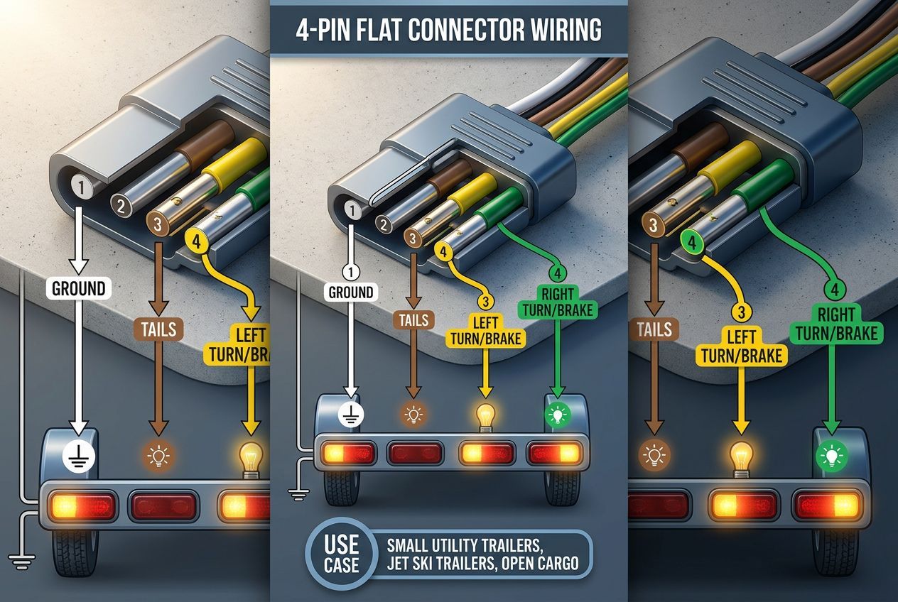

4-pin flat trailer connector wiring diagram showing ground tail left turn and right turn connections
πŸ”§
DIY TOWING & FLAT TOWING

What Is the 7-Pin Trailer Wiring Diagram?

The 7-pin RV-style connector is the standard for travel trailers, larger boat trailers, car haulers, and any trailer with electric brakes and onboard electrical systems. It's the connector you'll find factory-installed on most trucks and full-size SUVs.

7-Pin RV Connector Pinout (looking at the plug face, pins numbered clockwise):

What Is the 7-Pin Trailer Wiring Diagram? β€” data table
Pin Wire Color Function Typical Wire Gauge
Center White Ground 10 AWG
1 Brown Tail / Running Lights 14 AWG
2 Yellow Left Turn / Brake 14 AWG
3 Green Right Turn / Brake 14 AWG
4 Blue Electric Brakes 12 AWG
5 Red/Black 12V Auxiliary Power 10 AWG
6 Purple/Orange Reverse Lights 14 AWG

The 7-pin connector carries everything the 4-pin does plus three additional circuits. The blue wire sends the modulated brake signal from your tow vehicle's brake controller to the trailer's electric brakes. The red or black 12V auxiliary wire charges the trailer's battery and powers the breakaway switch. The purple or orange wire activates the trailer's reverse lights when you shift into reverse.

Ground wire gauge matters. The center ground pin carries the return current for all seven circuits simultaneously. A thin 16 AWG ground wire will create voltage drop that dims your lights and weakens your brake signal. Always use 10 AWG minimum for the ground β€” 8 AWG is better for trailers over 25 feet.

Key Insight: The 12V auxiliary power circuit (Pin 5) is live whenever the tow vehicle is running. It typically supplies 30-40 amps and charges the trailer's deep-cycle battery through the umbilical cord. If your trailer battery isn't charging while towing, this wire or its fuse is usually the culprit.

Try Our Free Truck Towing Capacity Lookup


7-pin RV trailer connector wiring diagram showing all seven pins with wire colors and functions
πŸ›‘οΈ
DIY TOWING & FLAT TOWING

How Do 5-Pin and 6-Pin Connectors Differ from 4 and 7?

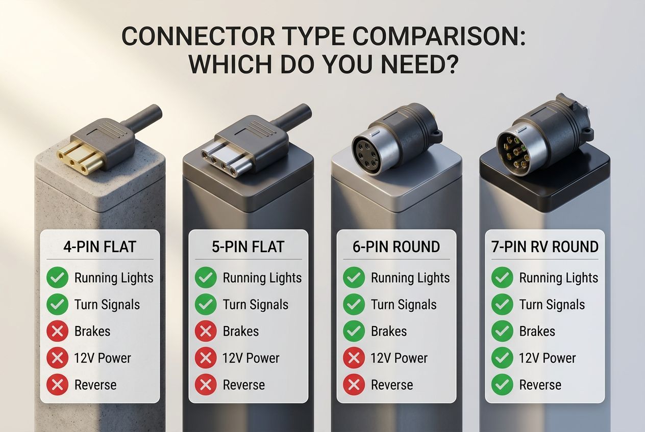
The 5-pin and 6-pin connectors fill the gap between basic 4-pin lighting and full-featured 7-pin setups. They're less common but serve specific needs.

5-Pin Flat Connector adds one wire to the 4-pin layout:

How Do 5-Pin and 6-Pin Connectors Differ from 4 and 7? β€” data table
Pin Wire Color Function
1-4 Same as 4-pin Ground, Tails, Left, Right
5 Blue Hydraulic surge brake lockout (or electric brakes)

The 5-pin is most common on boat trailers with hydraulic surge brakes. The blue wire connects to a solenoid that locks out the surge brakes when the tow vehicle reverses β€” preventing the trailer brakes from engaging when you're backing down the boat ramp.

6-Pin Round Connector adds two wires to the 4-pin base:

How Do 5-Pin and 6-Pin Connectors Differ from 4 and 7? β€” data table
Pin Wire Color Function
1-4 Same as 4-pin Ground, Tails, Left, Right
5 Blue Electric brakes
6 Red/Black 12V auxiliary power

The 6-pin provides electric brake control and battery charging but skips the reverse light circuit. It's common on older horse trailers, livestock trailers, and some enclosed cargo trailers from the 1990s and 2000s. Most newer trailers in this category have switched to the 7-pin RV standard.

Pro Tip: If your trailer has a 6-pin connector and your truck has a 7-pin, you can buy a 6-to-7 pin adapter for under $15. You'll lose reverse lights on the trailer, but brakes and charging will work. For full functionality, rewire the trailer to 7-pin β€” it's a one-afternoon job.


Trailer connector comparison showing 4-pin 5-pin 6-pin and 7-pin capabilities side by side

πŸ“‹
DIY TOWING & FLAT TOWING

How Do You Wire a Trailer Connector Step by Step?

Wiring a trailer connector from scratch requires basic tools and about 2-3 hours for a first-timer. Here's the process for a 7-pin installation β€” scale down for 4-pin by skipping the brake, auxiliary, and reverse circuits.

Tools needed: Wire strippers, crimping tool, heat shrink connectors (not electrical tape), 12V test light, zip ties, a 7-pin connector kit, and the correct gauge wire (10 AWG for ground and 12V power, 12 AWG for brakes, 14 AWG for lights).

Step 1: Run wires from the tow vehicle to the hitch. Mount the 7-pin socket on the hitch or bumper area. Route wiring along the frame rail, secured with zip ties every 12-18 inches. Keep wires away from exhaust components, moving suspension parts, and the driveshaft.

Step 2: Connect the ground wire first. Attach the white ground wire to a clean, bare-metal point on the vehicle frame near the hitch. Sand or grind the mounting point to remove paint and rust. Use a ring terminal with a self-tapping screw or existing bolt. A bad ground causes more problems than all other wiring issues combined.

Step 3: Tap into the vehicle's lighting circuits. Use a T-connector harness specific to your vehicle (available from Curt, Hopkins, or Tekonsha) rather than splicing into factory wires. T-connectors plug into the existing taillight harness and provide a separate output for the trailer without modifying the vehicle's wiring.

Step 4: Connect the brake controller wire. Run the blue wire from the 7-pin socket to the brake controller inside the cab. Most brake controllers mount under the dash and tap into the vehicle's brake light switch circuit. Use 12 AWG wire for runs over 15 feet.

Step 5: Connect 12V auxiliary power. Run the red or black wire from the 7-pin socket to the tow vehicle's battery through a 40-amp circuit breaker or fuse. This wire charges the trailer battery and must handle sustained current β€” don't tap into an existing circuit.

Step 6: Connect reverse lights. Tap into the tow vehicle's reverse light wire (usually at the taillight harness) and run to Pin 6. Use a 14 AWG wire and a heat-shrink butt connector.

Step 7: Test every circuit. With the trailer connected, test each function: running lights, left turn, right turn, brakes (all lights on), reverse, and trailer brakes using the manual override on the brake controller.

Common Mistake: Using electrical tape instead of heat shrink connectors. Electrical tape unravels in heat and moisture β€” the two things trailer wiring encounters constantly. Heat shrink with adhesive lining creates a waterproof seal that lasts years. The $10 difference in materials saves you from troubleshooting corroded connections later.


βš™οΈ
DIY TOWING & FLAT TOWING

How Do You Troubleshoot Trailer Wiring Problems?

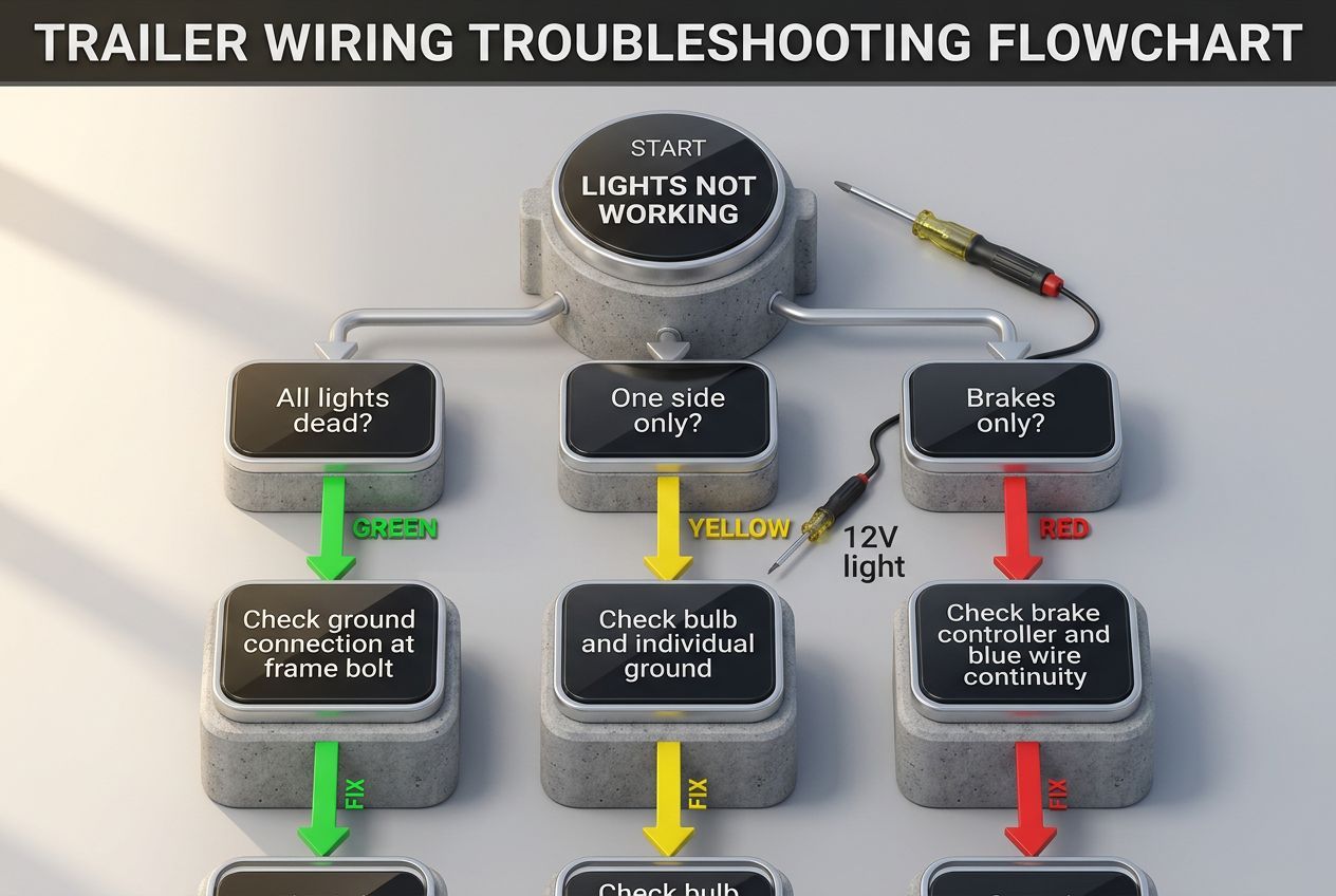
Trailer wiring fails more than any other towing component. Road spray, salt, mud, and vibration take a toll on connectors and splices. Here's a systematic approach to finding and fixing the most common failures.

Problem: All trailer lights are dead. Check the ground first. Disconnect the trailer plug and test the vehicle-side socket with a test light. If the socket has power on all pins but the trailer lights don't work, the trailer's ground connection is corroded or broken. Find where the white wire grounds to the trailer frame and clean or replace the connection.

Problem: One side isn't working (left or right). This is almost always a bad bulb or a corroded ground on that specific light housing. Trailer lights ground through the mounting bolts into the frame. If corrosion builds up between the light housing and the frame, that side loses its ground path. Remove the light, sand the mounting surface, and reinstall.

Problem: Turn signals work but brake lights don't (or vice versa). On a 4-pin system, these share the same wire, so the issue is likely a bad bulb with only one filament burned out. On vehicles with separate brake and turn circuits, check whether the converter module (required for some European vehicles) is functioning.

Problem: Electric brakes not working. Test the blue wire at the 7-pin socket with a test light while someone presses the brake pedal. If there's no signal, the brake controller has lost power or the wire between the controller and socket is broken. Check the brake controller fuse first β€” it's the most common cause.

Check your trailer sway control system if brakes are intermittent β€” some sway control systems interact with the brake circuit.

Key Insight: Carry a spare 7-pin connector, a test light, and a small bag of heat-shrink butt connectors in your tow vehicle. These three items solve 90% of roadside trailer wiring failures. A $20 kit can save you a $150+ roadside assistance call.


Trailer wiring troubleshooting flowchart for dead lights one side failure and brake issues

Sources & Methodology

  1. 1.
    SAE J2863 Standard β€” Official wire color and connector pinout specifications for trailer electrical systems.
  2. 2.
    FMCSA Trailer Lighting Regulations β€” Federal requirements for trailer lighting, reflectors, and electrical connections.
  3. 3.
    Hopkins Towing Solutions β€” Comprehensive wiring guides and connector specifications for all standard trailer plug types.
  4. 4.
    Curt Manufacturing β€” Technical installation guides for trailer wiring harnesses and T-connectors.
  5. 5.
    NHTSA FMVSS No. 108 β€” Federal Motor Vehicle Safety Standard covering trailer lighting requirements.

TowingServiceHub is reader-supported: we may earn money from ads and from some links on this page. See our editorial policy.

Mark β€” Founder & Editor

Mark

Founder & Editor

Mark is the founder and editor of TowingServiceHub, which he launched in 2026 after struggling to find clearly sourced towing costs and truck specs. He works in enterprise technology and tows his own boats, trailers, and equipment, so he knows the questions drivers actually ask.

Read full bio β†’

Need a tow truck right now?

Browse vetted local providers in your area. Real Google ratings, verified business info, free to use.

Or browse all 50 states from our directory

Frequently Asked Questions

Standard trailer wiring colors are white for ground, brown for tail/running lights, yellow for left turn/brake, and green for right turn/brake. On 7-pin connectors, blue is electric brakes, red or black is 12V auxiliary power, and purple or orange is reverse lights. Always verify with a test light before connecting.

A 4-pin connector handles basic lighting: ground, tail lights, left turn/brake, and right turn/brake. A 7-pin adds electric brake control, 12V auxiliary power for charging trailer batteries, and reverse lights. Use 4-pin for small utility trailers and 7-pin for travel trailers, boat trailers with brakes, or any trailer with electric brakes.

Yes. You can install a 4-to-7 pin adapter for basic lighting functions, but the adapter won't provide electric brake power, 12V auxiliary, or reverse light signals. For full 7-pin functionality, you need to run additional wires from the tow vehicle's brake controller, battery, and reverse light circuit to the 7-pin connector.

The most common causes are corroded ground connections, blown fuses, damaged wiring from road debris, or mismatched connector pins. Start by cleaning the ground wire connection on the trailer frame, then check each pin with a 12V test light. Corroded grounds cause more trailer lighting failures than any other single issue.

Yes. Electric trailer brakes require the dedicated blue wire in a 7-pin connector to receive the brake signal from your tow vehicle's brake controller. A 4-pin connector does not include a brake circuit. If your trailer has electric brakes, you must have a 7-pin connector and a brake controller installed in the tow vehicle.

Related Articles

Explore More Towing Guides

Browse all 157 expert guides and 10 free tools.